NES64 Instructions
Kit Contents / Parts to Buy
 If you bought the NES64 as a kit, you have all the below components already and you are ready to go.
If you only bought the board, or you had it printed yourself, you will need to get the below as well.
If you bought the NES64 as a kit, you have all the below components already and you are ready to go.
If you only bought the board, or you had it printed yourself, you will need to get the below as well.
- The NES64 board itself.
- NES controller casing, either from an original NES controller or a more current reproduction. Most
reproductions are made to (nearly) the same specifications as the originals. Bought kits contain a
reproduction casing.
- A cable w/plug. Original NES controllers came with around 2 m of cable, but you may of course get any
length you like. There are several options:
- Get a new reproduction Amiga/Atari joystick extension cable and cut off the male plug. These come in
different qualities from e.g. Ebay and Amazon. Some contain cable that is apparently a bit too stiff
for some people's taste, but the ones I have come across are very similar to original joystick/pad cable.
This is what current kits come with.
- Get a cable from a broken and otherwise non-salvageable Atari/Commodore joystick, or even from a new
reproduction joystick. They come relatively cheap from e.g. Ebay and Amazon.
- Assemble your own plug and attach your favourite cable. Instructions
for two alternatives are provided on the website.
- 2-position right angle slide switch, SPDT On-On, 3 pins (or 5 pins with two shielding pins),
2 mm pin pitch, min 5 mm knob height. These should come cheaply
from your local electronics store or even from EBay.
- Basic soldering skills and tools/equipment. These do not come with the kit! ☺
Assembly Instructions
Assembling the board and mounting it into a case is relatively easy. However, some basic soldering skills
are required, as well as some equipment such as a soldering iron, wire strippers, etc. Here are the steps:
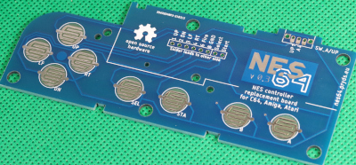
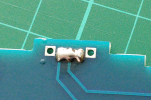
 Solder the switch to the top right of the board. This
switch will allow you to change what is perceived as "up" by the computer,
toggling between the actual "up" direction of the D-pad (joystick style jumping) and button A (NES
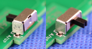
controller style jumping). Please note, you may position the switch pointing either way, depending on
whether you are willing to destructively modify your controller case or not:
Solder the switch to the top right of the board. This
switch will allow you to change what is perceived as "up" by the computer,
toggling between the actual "up" direction of the D-pad (joystick style jumping) and button A (NES
controller style jumping). Please note, you may position the switch pointing either way, depending on
whether you are willing to destructively modify your controller case or not:
- Let the switch lever point away from the board to be able to change the setting from the outside
of the controller. This is only recommended for new reproduction controllers which can easily be
replaced, as you need to cut a part of the case top, or drill a hole in it.
- Let the switch lever point towards the centre of the board if you don't want to modify
your controller in a destructive way. This option will let you restore the controller back to its
original state at a later point if you wish. This is recommended for use with original controllers.
The downside is, of course, that you need to open the controller if you want to change the setting.
 Or don't mount the switch at all if you want to permanently
set which button triggers the "up" action. Bridge the middle solder pad (of where you would otherwise
mount the switch) to the solder pad marked either "UP" or "A", depending on your choice. Or bridge all
three solder pads if you want to simultaneously enable both buttons.
Or don't mount the switch at all if you want to permanently
set which button triggers the "up" action. Bridge the middle solder pad (of where you would otherwise
mount the switch) to the solder pad marked either "UP" or "A", depending on your choice. Or bridge all
three solder pads if you want to simultaneously enable both buttons.
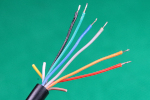
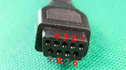 You need to figure out which lead is connected to which connector pin. This is best done by simply
holding a multimeter to each pin in succession and test for continuity with the leads. Please note that
lead colours differ between cables. I have had cables from the same batch that had the leads connected
differently to each other in the plug.
You need to figure out which lead is connected to which connector pin. This is best done by simply
holding a multimeter to each pin in succession and test for continuity with the leads. Please note that
lead colours differ between cables. I have had cables from the same batch that had the leads connected
differently to each other in the plug.
| Connector pin | 1 | 2 | 3 | 4 | 6 | 8 |
|---|
| Board pad | 1 UP | 2 DN | 3 LF | 4 RT | 6 Fire | 8 GND |
|---|
| Lead colour | May differ from cable to cable. Measure them! |
|---|
-
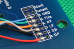
Strip the insulation off the cable and tin the leads. Solder the 6 leads mentioned above to the
back-side of the board according to the table. Please note, your lead colours may be different
to the picture shown here. Make sure to match them up correctly, or you may
break your vintage computer! Pins 5, 7 and 9 and corresponding leads are not used.
The pads labelled "Select" and "Start" are not used for this application but are supplied on the board
for convenience with other uses.
- Open your NES controller by unscrewing the 6 small screws from the backside and gently removing the
back cover. Do not tilt the controller, or the buttons may fall out. Remove the existing PCB and cable,
if any, by gently lifting it off the plastic pegs.
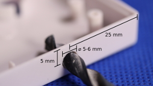 If you chose to point the switch outwards earlier, you will need to cut
or drill a hole in the top part of the case for the switch lever to stick through. The centre of the hole
needs to be 25 mm from the right side of the case, and 5 mm from the top. The hole itself needs to be
5-6 mm wide.
If you chose to point the switch outwards earlier, you will need to cut
or drill a hole in the top part of the case for the switch lever to stick through. The centre of the hole
needs to be 25 mm from the right side of the case, and 5 mm from the top. The hole itself needs to be
5-6 mm wide.
Instead of drilling a hole, you may want to use an X-Acto knife or similar to cut a section out of the
case, corresponding to the drilled hole and upwards. This will make it slightly easier to make the
position of the hole fit the switch, but a drilled hole will usually end up looking nicer.
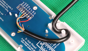 Mount the NES64 board in the casing, making sure to let the
cable snake around the two plastic pegs as a strain relief. Notice that the PCB will need to rest on
some of the stand-offs, while other standoffs will need to fit through holes in the PCB. This will
vary from casing to casing. If you encounter a NES casing that the NES64 will not fit into, please let
me know so I can decide if I need to make future revisions fit that particular type of casing.
Close the two casing halves and add back all screws.
Mount the NES64 board in the casing, making sure to let the
cable snake around the two plastic pegs as a strain relief. Notice that the PCB will need to rest on
some of the stand-offs, while other standoffs will need to fit through holes in the PCB. This will
vary from casing to casing. If you encounter a NES casing that the NES64 will not fit into, please let
me know so I can decide if I need to make future revisions fit that particular type of casing.
Close the two casing halves and add back all screws.
Good luck with your new NES controller for your Commodore / Atari retro computer (or compatible)!
nes64.autumnhippo.com