The NES64 instruction sheet assumes you have a ready-to-use cable with a 9-pin joystick plug already attached to one end. This is by far the easiest and most compatible solution. However, these cables can be a bit harder to obtain, especially if you don't want to take one from an existing joystick, thereby rendering the joystick unusable.
If you would prefer to make your own plug, here are two ways of doing so. The parts should be quite easy to get by. Alternative 1 is easier to assemble, but there are some classic computers that it will not fit into. Alternative 2 will fit in all compatible computers, but the assembly is more complicated.
You need:
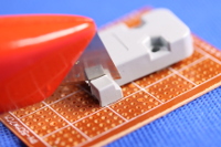
If your D-sub connector is of the wide kind which has "wings" and fastening screws in the sides, you will probably have to trim off these wings. Otherwise the connector will most likely be too wide to fit in the game ports of a Commodore 64 or Amiga -- especially two at a time. Take a measurement to see whether it will fit in your specific retro computer, and if it does, you can of course use the plug as-is.


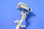
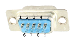 Strip both ends of the cable, and tin the ends. Solder the 6 leads
to the D-sub connector, so that each of the pins 1, 2, 3, 4, 6 and 8 have a lead soldered to it. The
remaining pins are not used.
Strip both ends of the cable, and tin the ends. Solder the 6 leads
to the D-sub connector, so that each of the pins 1, 2, 3, 4, 6 and 8 have a lead soldered to it. The
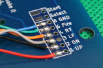
remaining pins are not used.| Connector pin | 1 | 2 | 3 | 4 | 6 | 8 |
|---|---|---|---|---|---|---|
| Board pad | 1 UP | 2 DN | 3 LF | 4 RT | 6 Fire | 8 GND |
This guide will show you how to make a more advanced plug where the pieces of plastic described above are replaced by a metal wire pull strain relief. This will be necessary if your computer has a recessed connector, such as several Amigas. It should fit everywhere an original joystick plug does.
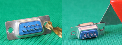 The connector consists of two metal plates that are "riveted"
together at each of the two holes. Drill out these two holes, insert a knife or another sharp object in
between, and then very carefully pry the two metal plates from each other. Do not disassemble the blue
plastic part.
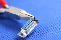
 Using a pair of pliers, bend the sides of the larger metal bearing
piece to ninety degrees as close to the extruded part as possible. You can throw the other metal piece with the
smaller extrusion away as that will not be needed.
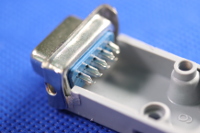
Trim the sides of the blue plastic plug with a sharp knife or a file so that it becomes rectangular shaped
and fits snugly in between the two bent metal "wings".
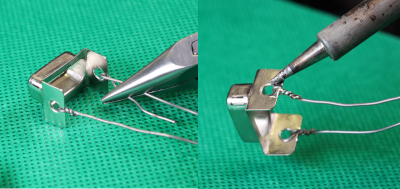 Attach two pieces of thin metal wire—one through each hole—which
is going to act as a pull strain relief. Use a pair of pliers to twist the wire as tightly and as closely to
the hole as possible. Snip off any excess wire and add a small bit of solder to secure the wire twist. Try not
to make the twist and solder blob too bulky, but instead as small as possible while still retaining its
strength, keeping in mind that it must fit into the plastic casing in the end.
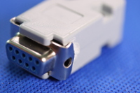
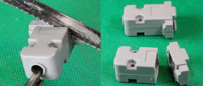 With a fine saw, cut the plastic casing in half, immediately behind
the "wings". Make sure to cut off only enough so that there is still enough room in the case to fit the actual
plug and its leads. Smooth out any rough plastic edges after the saw with a small file or a sharp knife.
 On both halves of the casing, mark where the twisted metal wire
goes, and with a sharp knife or similar cut away enough plastic for it to fit. On one of the halves, only,
mark up and drill two small holes near the back end of the casing, only just big enough for the metal wire
to pass through smoothly. Fit the extruded metal bearing part into the casing and let the metal wires through
the two holes. Straighten the wires as much as possible, making sure they go around the casing screw
hole pillars.
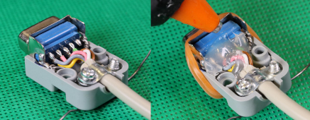 Solder the leads to the plug as per the Alternative 1 instructions
above and add the small strain relief metal bracket to the cable.
You might need to add a piece of excess cable isolation or similar for the bracket to get a good grip of the
cable. Then fit the plug assembly into the metal bearing and casing. While holding the plug and casing tightly
together (for instance by means of a rubber band), add as much hot glue as will fit behind the plug. Make sure
to add glue beneath and between the leads as well, not just on top.
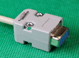 While the metal wires act as a pull strain relief, the glue will act
as a push strain relief. Cut any excess hot glue away with a sharp knife after it has cooled down in case
you added too much for the casing to be able to close properly.
While the metal wires act as a pull strain relief, the glue will act
as a push strain relief. Cut any excess hot glue away with a sharp knife after it has cooled down in case
you added too much for the casing to be able to close properly.nes64.pryds.eu